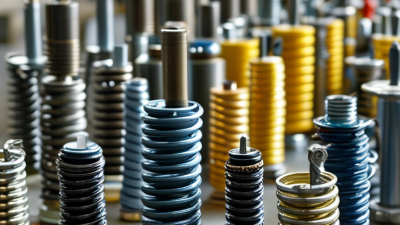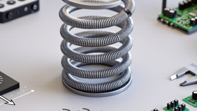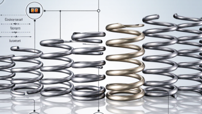
A Contact Spring may be only a few millimeters long, yet it can determine whether a device maintains a steady electrical connection. In a battery compartment, a coiled spring presses against a cell terminal. Inside a compact connector, a shaped metal contact may flex repeatedly as parts move. These details affect contact force, available travel, resistance, and service life. Small parts matter.
Common types include compression springs, leaf springs, cantilever contacts, battery springs, and spring-loaded pins. Each suits different space and movement requirements. Compression designs provide axial force, while leaf and cantilever forms flex sideways or at a fixed end. Spring-loaded pins can support repeated connections, but their travel and current ratings need careful review. The names alone do not tell the whole story.
This guide compares the main contact spring types and explains where each may work best. It considers shape, material, installation, operating conditions, and practical limits. A stainless steel spring may resist corrosion, for example, while copper alloys can offer useful electrical conductivity. The right choice still depends on the design and the manufacturer’s specifications. There is no universal winner. A tidy chart can make selection seem simpler than it is; real assemblies may reveal awkward fit or inconsistent pressure. Reviewing drawings and testing a sample under expected conditions can uncover those problems before production.
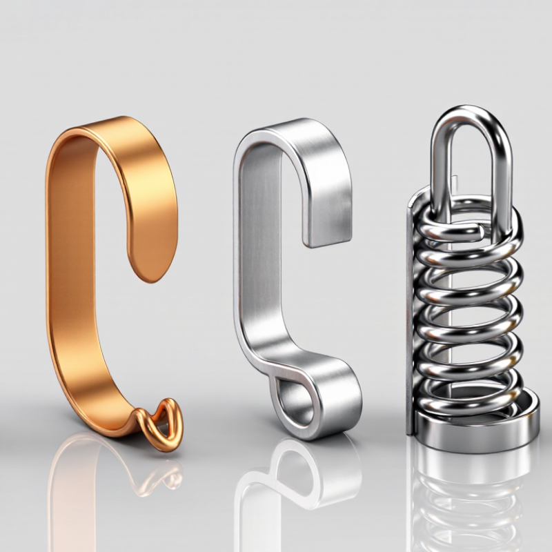
Contact springs are elastic conductors that keep two surfaces electrically connected despite vibration, movement, or small manufacturing variations. Their spring force helps maintain contact; their metal carries current. Common forms include cantilever beams, coil springs, leaf contacts, and multi-finger “crown” contacts. Each suits different travel, space, and current needs. Small parts. Big consequences.
The details matter. Too little force can raise contact resistance, while excessive force can wear plating or deform a mating surface. IEC 60512-2-1 defines a millivolt-level method for measuring contact resistance, helping engineers compare connection performance under controlled conditions. The U.S. Geological Survey’s Mineral Commodity Summaries 2024 reports about 22 million metric tons of global copper mine production in 2023. Copper alloys are widely used in spring contacts, but conductivity alone does not determine performance; geometry, temper, finish, and operating temperature matter too. A spring that works on a bench may behave differently after repeated cycling. That gap deserves testing, not guesswork.

What Are the Top Types of Contact Springs?
Key Design Factors That Shape Contact Spring Performance
Contact springs include coil, leaf, and stamped-beam designs. Each handles movement and force differently. A coil spring suits repeated compression, while a leaf contact can fit a low-profile assembly. The right choice depends on the available space, required travel, and how firmly the parts must connect. A spring that feels sturdy by hand may still lose contact inside a vibrating device.
Material and geometry shape performance. Spring alloys need enough elasticity to return after compression, while contact surfaces may need plating to limit wear or corrosion. Designers also consider wire thickness, beam length, bend radius, and working deflection. Small changes matter. Too much force can damage a mating surface; too little can cause intermittent contact. Temperature and repeated cycling deserve attention, too. A drawing may look correct, yet the real assembly can behave differently.
Tips: Check force across the full travel, not just at one point. Test samples in the actual housing, especially under vibration and temperature changes. Keep notes on wear patterns; they can reveal a design weakness. Sometimes the first prototype misses something. That is useful feedback.
Calculated spring-rate example for a round-wire helical contact spring
How to read it: For this example, the mean coil diameter is 10 mm, there are 5 active coils, and the steel shear modulus is 79 GPa. Spring rate is calculated using k = Gd⁴/(8D³n); increasing wire diameter therefore raises spring rate sharply.
Common contact spring types include helical coil, leaf or cantilever, wave, stamped-and-formed, and pogo-pin contacts. Geometry, material, working deflection, fatigue life, and required contact force all influence performance. The plotted values are theoretical for the stated helical-spring assumptions, not universal ratings for these spring types.
Contact springs maintain an electrical path when two parts meet, even if vibration or small gaps interrupt contact. Their shape determines how they flex and where force is applied. A leaf spring is a thin strip fixed at one end, with a free tip pressing against a mating surface. It is often stamped from copper alloy, then formed and plated for conductivity and wear resistance. Simple, but sensitive to alignment.
Coil springs use wound wire to provide axial force in a compact space. Pogo pins combine a spring-loaded plunger, barrel, and internal coil, making them useful where repeated compression is needed. Wire-form springs bend into custom shapes, while leaf contacts can be designed with several contact points. Material thickness, temper, plating, and working travel all affect performance. A spring that is too stiff may damage its counterpart; one that is too soft may lose reliable contact. That trade-off is easy to underestimate.
Tips: Check the available travel and mating force in the actual assembly, not only on a drawing. Look for wear or discoloration after cycling. Small details matter. Plating can wear through, and tolerances can stack up, so testing under realistic conditions is worth the extra effort. No design is perfect; revise it when test results disagree with assumptions.
Leaf springs suit flat, low-profile interfaces, such as battery doors and board-to-board contacts. Their broad contact area can tolerate slight alignment error, but repeated flexing may cause fatigue. Coil springs provide longer travel in compact spaces, making them useful in test fixtures and moving assemblies. They need careful guidance; an unsupported coil can buckle. Pogo-pin contacts combine a plunger and internal spring, offering controlled travel for charging pads and test probes. They are compact, but dirt or plating wear can raise resistance. Fit matters more.
Performance comparisons need consistent test conditions. IEC 60512-2-1 specifies a low-level contact-resistance method using up to 20 mV open-circuit voltage and 100 mA test current. These limits help assess contact resistance without relying on high-current measurements that may mask surface films. IEC 60512-9-1 covers mechanical operation testing, including repeated mating cycles; actual cycle requirements depend on the connector specification. That trade-off is easy to underestimate. In practice, compare resistance before and after cycling, spring force across working travel, and temperature rise at operating current. A leaf spring may win on simplicity, while a pogo contact may better handle frequent engagement. Neither is automatically more reliable: plating, alignment, contamination, and assembly tolerances can outweigh the spring geometry.
Choosing the right contact spring begins with the device’s actual connection, not its catalog label. Coil springs suit compact axial contacts, while leaf springs can provide a broad, low-profile contact. Pogo-style contacts offer controlled travel in tight spaces, but their moving parts need room and careful alignment. Wire-form springs can fit unusual shapes. Small details matter.
Check the available stroke, required contact force, current, and space around the spring. A spring that is too stiff may damage a small pad; one that is too soft can lose contact when the device vibrates. Measure the gap at both ends of the tolerance range, not just on one ideal sample. Also consider moisture, dust, and repeated compression, since these conditions can change performance over time.
Material and surface finish affect conductivity, wear, and corrosion resistance, so match them to the operating environment and verify them with a supplier or test data. That sounds simple. It isn’t always. Build a small prototype and measure contact resistance under realistic movement and load. If results vary, inspect alignment and mounting pressure before changing the spring itself. A spring can look correct and still behave poorly in the assembled device.
| Contact Spring Type | Typical Design | Common Applications | Key Advantages | Selection Considerations |
|---|---|---|---|---|
| Leaf or Finger Spring | A formed strip or array of flexible metal fingers that presses against a mating surface. | Grounding contacts, enclosure seams, battery contacts, and board-to-board connections. | Can provide multiple contact points and accommodate moderate misalignment or surface variation. | Check finger deflection, contact pressure, wear, and the available space. Multiple fingers may help maintain contact if one point is interrupted. |
| Coil Compression Contact Spring | A conductive helical spring compressed between two electrical contact surfaces. | Battery compartments, removable modules, and compact electrical assemblies. | Offers a simple way to maintain contact force over a defined compression range. | Confirm the working travel, force, solid height, fatigue life, and resistance to buckling. The spring's material and geometry affect electrical resistance. |
| Pogo Pin (Spring-Loaded Contact) | A plunger moves inside a barrel and is returned by a small internal spring. | Charging docks, test fixtures, removable accessories, and compact interconnects. | Provides a guided, repeatable contact with useful compliance in a small footprint. | Match the stroke and required force to the stack-up tolerance. Check contact resistance, current and temperature limits, mating-pad finish, and cycle life for the specific design. |
| Wave Spring Contact | A formed strip with a repeating wave profile that applies spring force when compressed. | Low-profile electrical interfaces, grounding assemblies, and applications with limited axial space. | Can deliver spring force in a relatively short installed height. | Verify the operating deflection, force consistency, lateral stability, and contact arrangement. Its electrical suitability depends on the material, finish, and current path. |
| Stamped-and-Formed Contact Spring | A sheet-metal contact shaped by stamping and bending, often with an integral spring feature. | Connectors, switches, battery terminals, and high-volume electronic assemblies. | Can combine the contact and spring functions in one part and is suitable for repeatable production. | Review forming tolerances, spring stress, contact area, burr direction, and plating coverage. Validate force and durability in the finished assembly. |
| Wire-Form Contact Spring | Conductive wire bent into a spring shape, such as a loop, clip, or formed contact. | Clips, grounding contacts, battery connections, and custom electrical interfaces. | Can provide a flexible, compact contact geometry with relatively simple construction. | Consider wire diameter, bend radii, stress concentration, contact stability, and the space needed for movement. Check that the contact remains secure under vibration. |
| Elastomeric Contact Connector | Conductive elements embedded in an elastomeric body; compression brings conductive paths into contact. | Display connections, keypad interfaces, and other low-profile connections between aligned surfaces. | Can connect closely spaced terminals without individual metal pins. | Requires controlled compression, accurate alignment, and suitable surface flatness. Confirm contact resistance, compression set, and environmental compatibility. |
| Material, plating, current capacity, contact resistance, and service life are design-dependent. Select a spring using the device's force, travel, space, electrical, environmental, and cycle-life requirements, then verify performance in the assembled device. | ||||